Verifying a part
A script that ran without an exception is not proof that the geometry is right. Check the timeline, the bodies, interference and screenshots after every step, and print a test piece.
Work in small steps and check each one before the next. This is the routine the rules for agents ask for, and it works the same by hand.
One step at a time
Put one feature, or a few related ones, in each script and run it with --atomic:
fusionctl run step-3-holes.py --atomicIf the script fails, the timeline items it added are deleted, newest first, and the model is back where it was before the step.
When a script fails
error: Script failed.
Traceback (script frames only):
  File "<fusion-cli>", line 4, in <module>
    root.features.extrudeFeatures.addSimple(sk.profiles.item(1), VS("10 mm"), adsk.fusion.FeatureOperations.NewBodyFeatureOperation)
                                            ~~~~~~~~~~~~~~~~^^^
RuntimeError: 3 : Bad index parameter
--atomic: rolled back 1 timeline item(s): Sketch1
The traceback shows only the frames of your script (<fusion-cli> for inline exec code, the file path for run). Here the script asked for a second profile in a sketch that has one; the sketch it had already created, Sketch1, was removed. The exit code is 1.
After every step
The timeline
Every item should be ok. A warning or error comes with Fusion's message in the last column.
#  feature       type            health       message
0  L profile     Sketch          ok
1  Bracket body  ExtrudeFeature  ok
2  Hole points   Sketch          ok
3  Base holes    HoleFeature     ok
4  Wall hole     HoleFeature     ok
5  Bend fillet   FilletFeature   ok
6  Bed chamfer   ChamferFeature  ok
The bodies
The body count, volume and bounding box should change the way the step intended. An operation that changed nothing failed silently.
body     where  solid  volume mm³  size mm       min mm       faces
Bracket  root   yes    6168.75     40 x 24 x 30  0 x -12 x 0     16
Measure the dimensions that matter against the spec. The bracket should be 40 x 24 x 30 mm and sit on the bed: min mm says z starts at 0. solid must be yes for anything you print. After params --set length=55mm hole_d=5.5mm the same row reads 7509.1 and 55 x 24 x 30 with 16 faces: longer, same topology.
Interference
For assemblies, check that no two visible solid bodies overlap:
No interference between 1 solid body.Zero overlap does not prove a fit. A peg can miss its hole by 2 mm without touching it: measure the gaps too, for example with a small exec script that compares bounding boxes.
Screenshots
Look before you say it is done. An isometric view plus front and top catches most mistakes: a hole on the wrong side, a fillet on the wrong edge, a part lying on its side.
fusionctl screenshot shot.png --view iso
fusionctl screenshot front.png --view front
fusionctl screenshot top.png --view top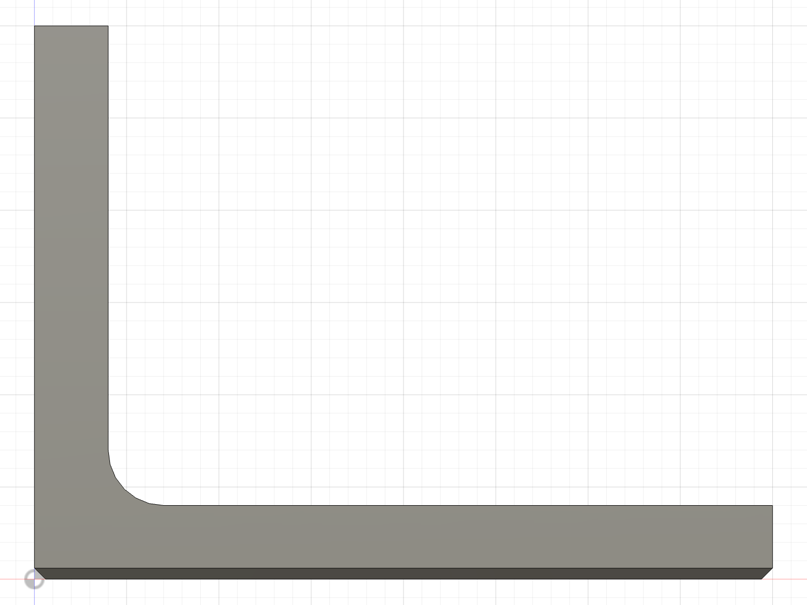
--view front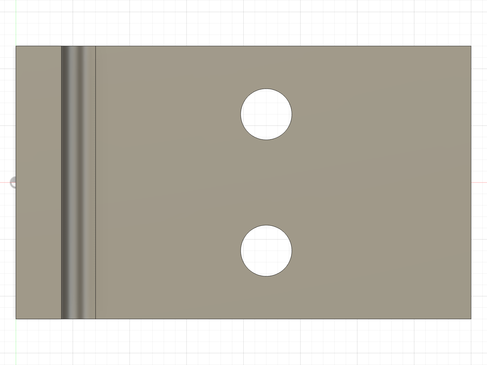
--view topA coding agent can read these PNG files back as images.
Fix the feature, not the symptom
When a native feature fails (a fillet, a pattern, a shell), fix it rather than replacing it with many manual cuts. The workaround leaves a timeline nobody can edit, and params --set stops working for that part of the model.
Before printing
- Export STEP as the source of truth, 3MF or STL for the slicer.
- Print a small test piece of any critical fit (a hole for a bearing, a snap, a thread) before the whole part.
- The bracket uses a 0.6 mm chamfer, not a fillet, on the edges that touch the bed, against elephant's foot.
Made by Lucas Piera. MIT licence. fusionctl is not affiliated with or endorsed by Autodesk; Autodesk and Fusion are trademarks of Autodesk, Inc.
Scripting in Fusion
The globals a fusionctl script gets, the API's centimetres, which way each sketch plane points, user parameters, and recipes taken from examples/bracket.py.
Assemblies and joints
Components, rigid and revolute joints, driving a joint, and interference and clearance checks, with the code of the recorded wristwatch in examples/watch.